

O-ring groove design decides how well an O-ring seals. The groove controls how much the O-ring is compressed, how much room it has to expand and swell and how well it is supported against pressure. An improperly sized groove can cause even the best compound to leak, extrude or fail early.
Good O-ring gland design balances squeeze, stretch and gland fill, along with clearance gap, tolerances, surface finish and gland edges.
Key Factors in O-Ring Groove Design:
The groove is the channel machined into one part. The gland is the complete cavity formed once the parts are assembled: the groove plus the surface that closes it. In O-ring gland design, squeeze and gland fill are always calculated on the assembled gland.
The main O-ring groove dimensions are gland depth, groove width and groove diameter. In O-ring groove sizing, gland depth sets the squeeze, groove width sets the gland fill and groove diameter sets the stretch.
O-Ring Gland Types:
● Male gland (piston seal): groove on a piston or shaft, sealing radially against the bore.
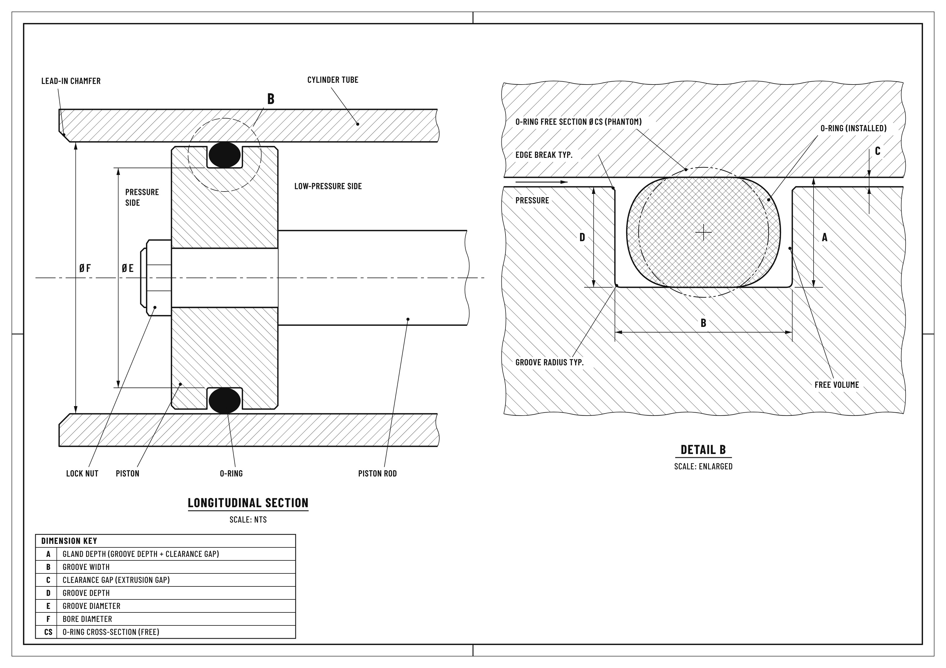
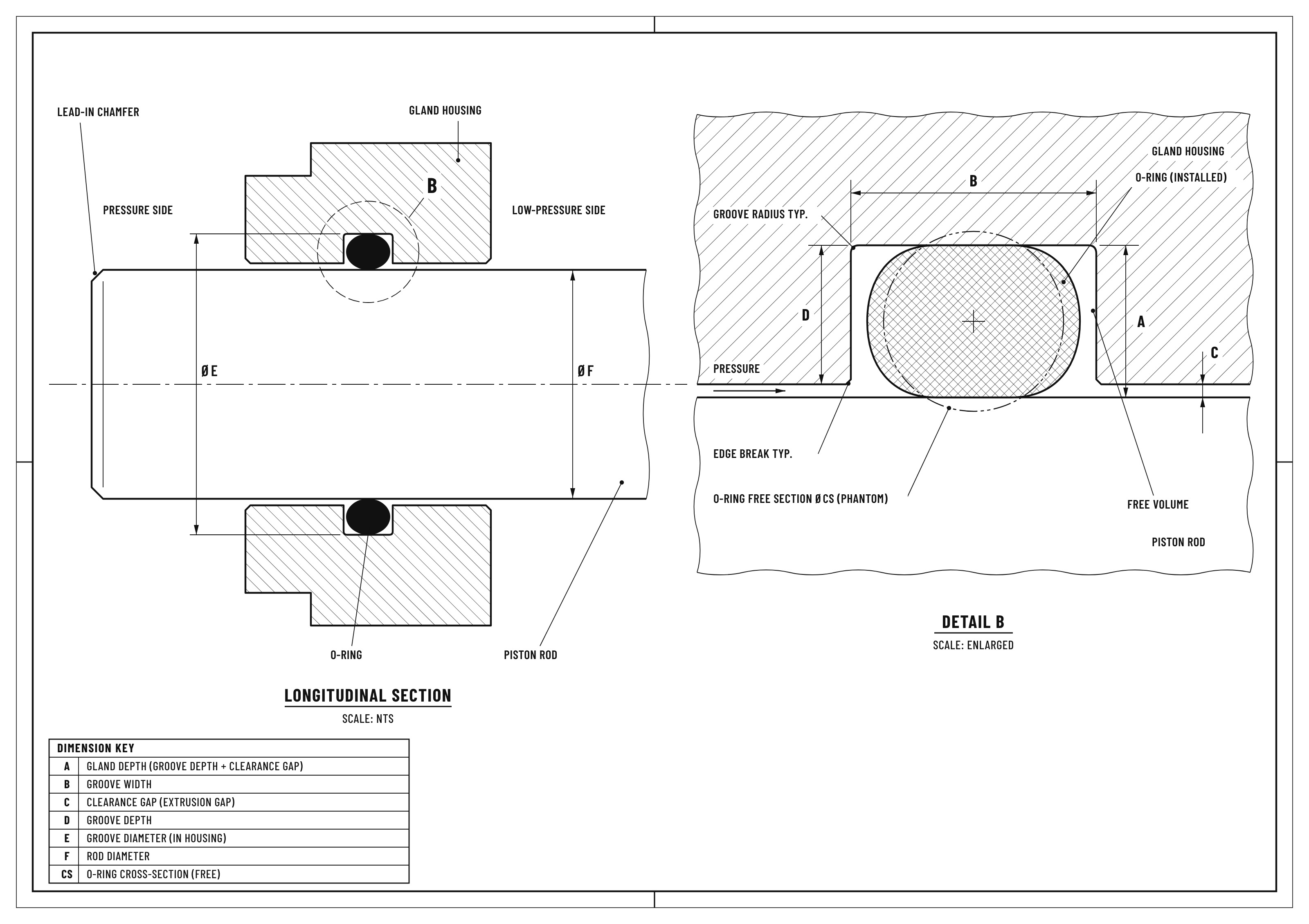
● Female gland (rod seal): groove inside a bore, sealing radially against a rod.
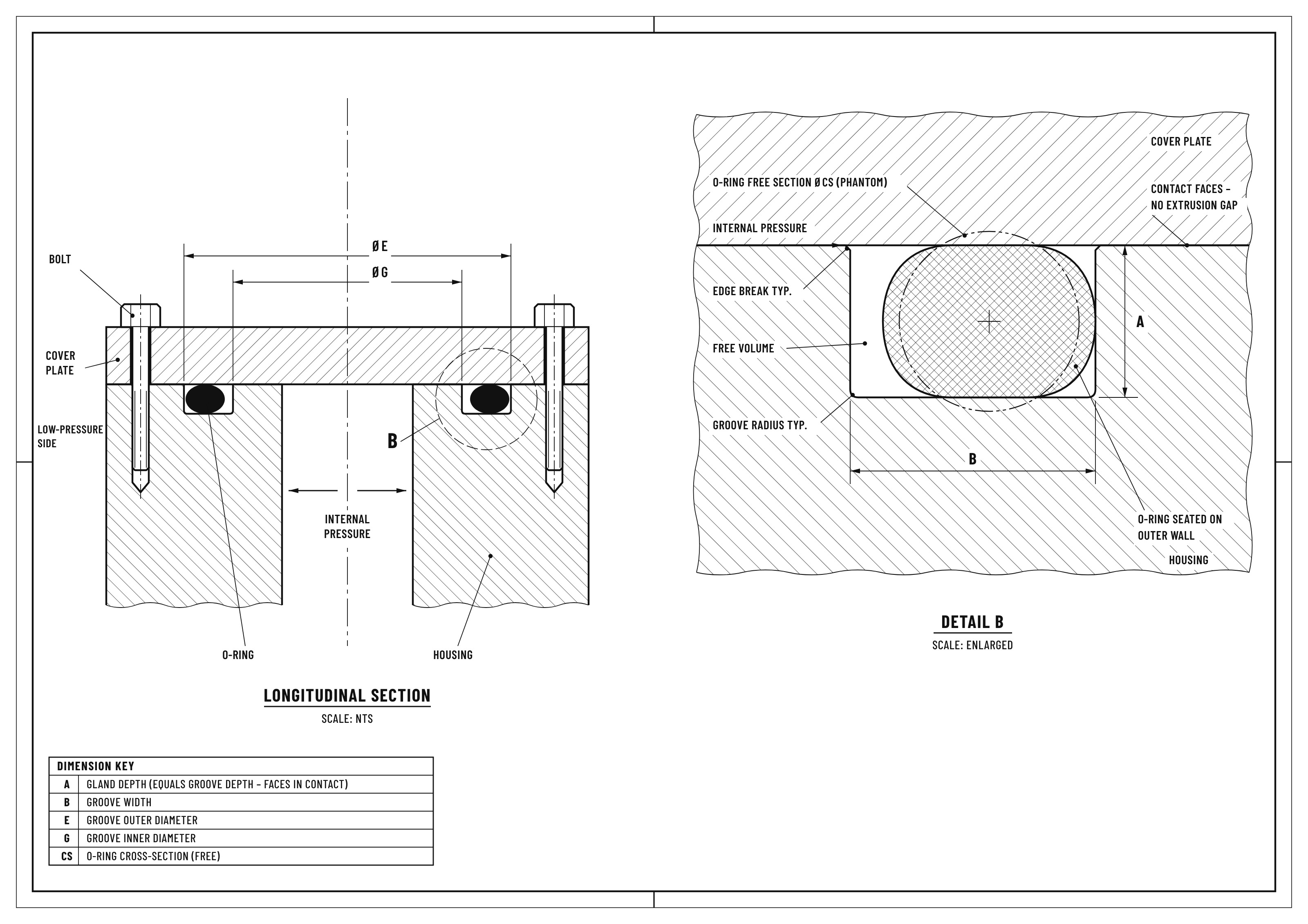
● Face seal: groove in a flat face, with the O-ring compressed axially like a gasket.
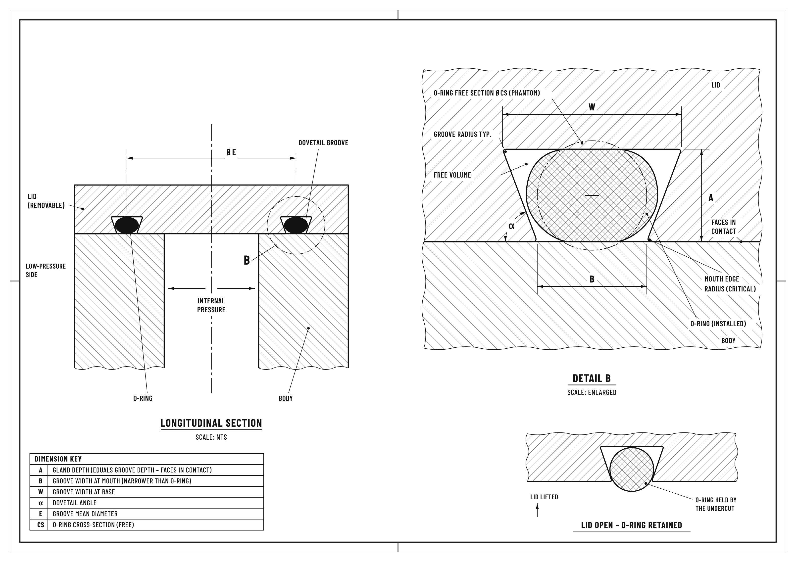
● Dovetail gland: undercut walls that hold the O-ring in place when a cover or valve is opened.
● Triangular (crush) gland: an angled chamfer that fully confines a single-use O-ring where space is tight.
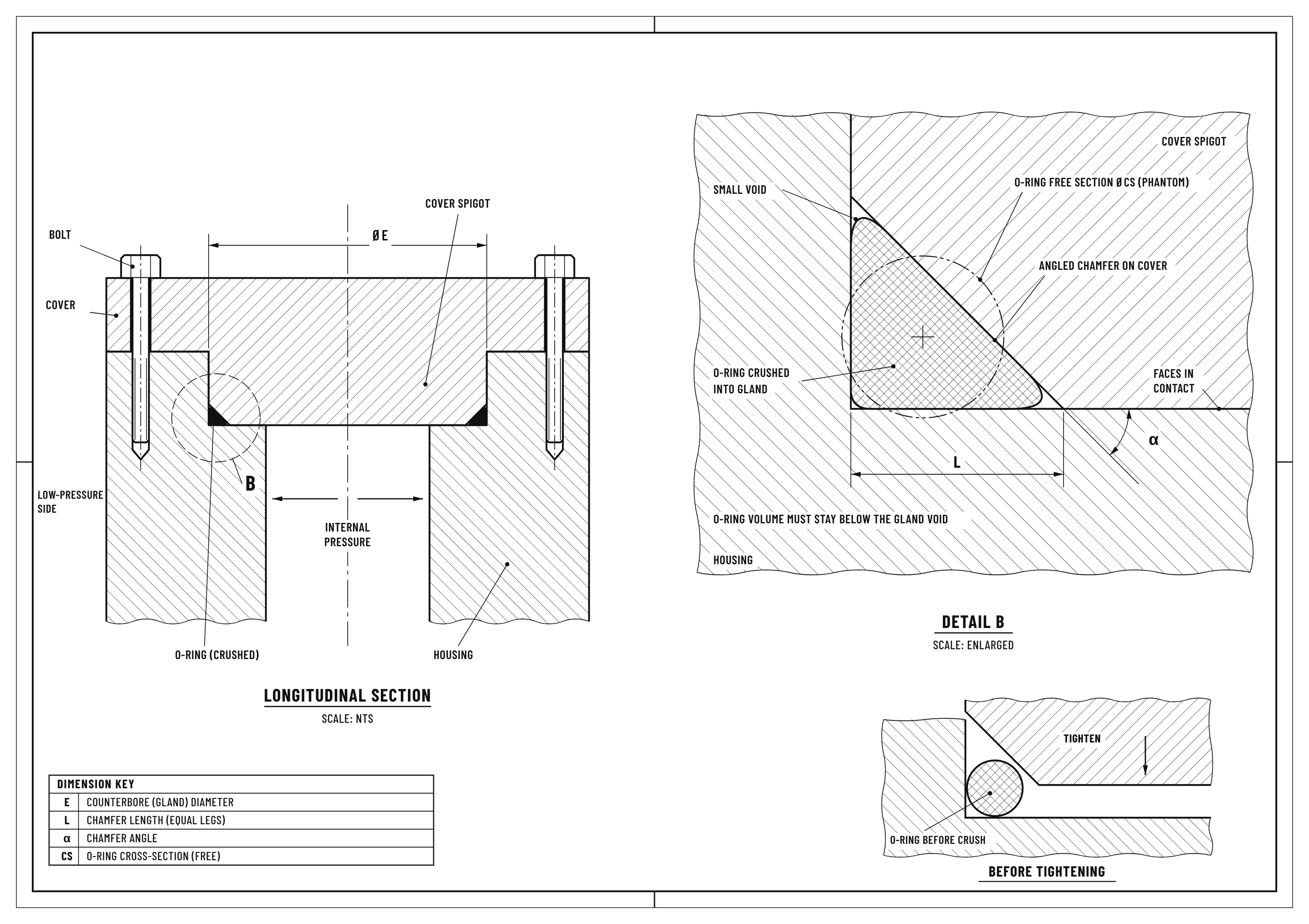
Static glands have no relative movement between parts. Dynamic glands see reciprocating, rotary or oscillating motion.
O-Ring Squeeze:
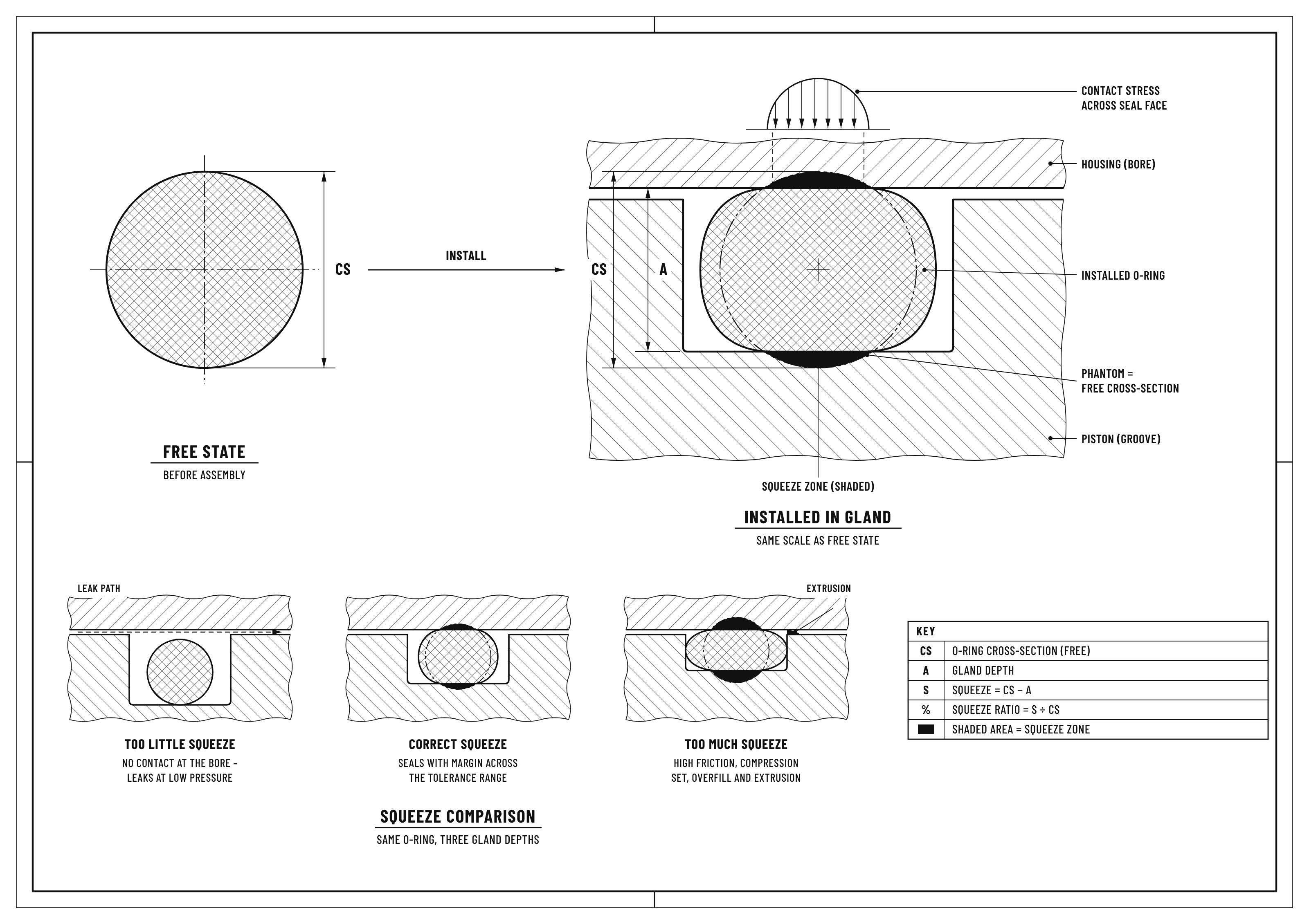
Squeeze is the reduction in O-ring cross-section when it is compressed between the groove bottom and the mating surface. It creates the contact stress that seals at low pressure and system pressure then add to it.
Calculation
General guidance
● In O-ring groove design, face seals run the highest squeeze, static radial seals a moderate squeeze, reciprocating seals a lighter squeeze and rotary seals the lightest.
● Smaller cross-sections need a higher percentage of squeeze to stay sealed across their tolerance range.
● Squeeze must never reach zero under any tolerance condition.
Too little squeeze can result in: leakage at low pressure, in cold conditions or under vacuum and loss of sealing force as compression set develops.
Too much squeeze can result in: cut O-rings at assembly, high friction and wear in dynamic seals, spiral failure and faster compression set.
O-Ring Installed Stretch:
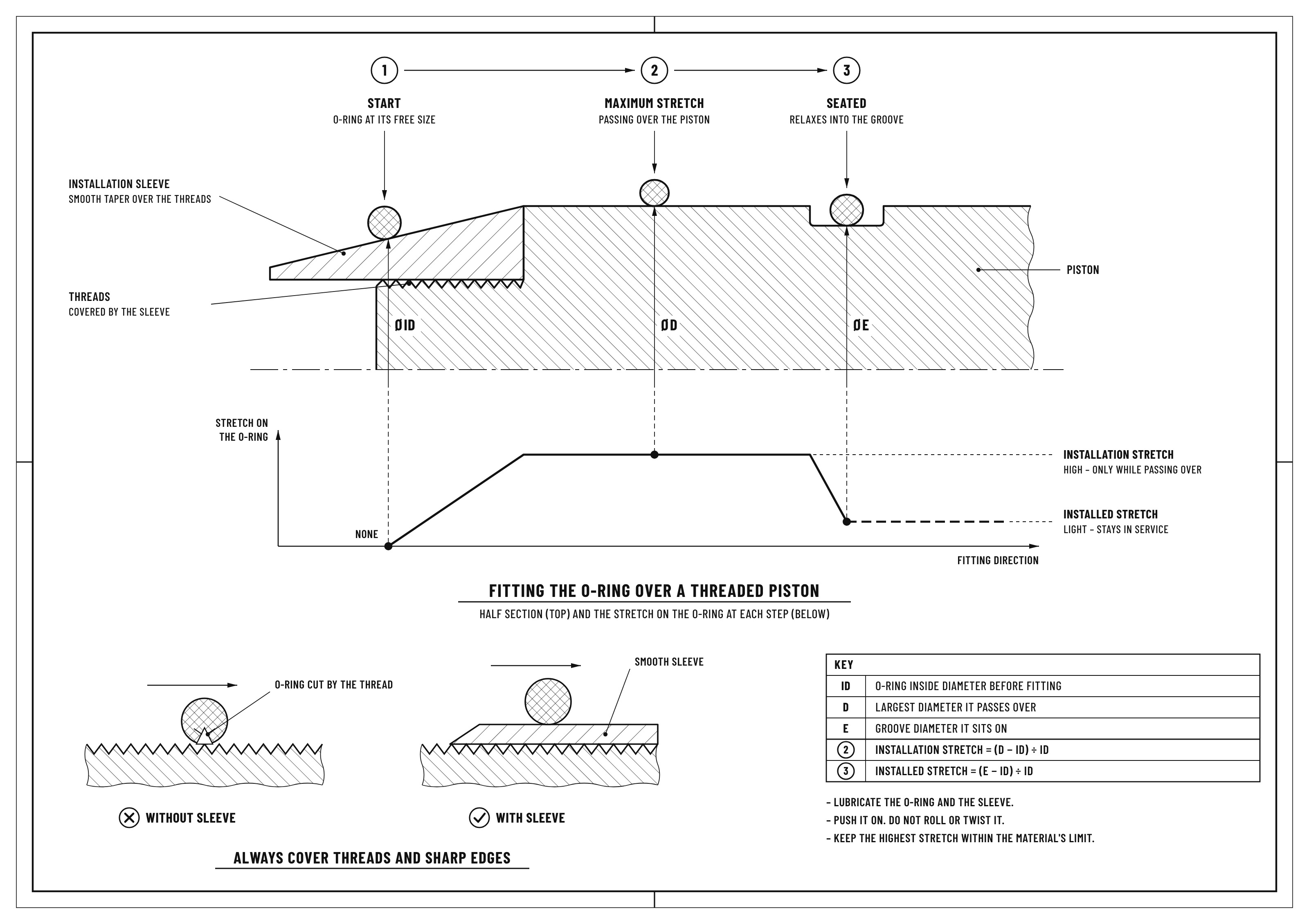
Installed stretch is the increase in O-ring ID when it is fitted into a piston groove. A light stretch holds the O-ring firmly at the groove bottom, so it does not roll or fall out during assembly.
Calculation
Stretch (%) = (groove diameter − O-ring ID) ÷ O-ring ID
General guidance
● Stretch should be kept light. It thins the cross-section, so the reduced cross-section should be used when squeeze is calculated.
● Where a higher stretch cannot be avoided, the gland depth should be reduced slightly to restore squeeze.
● In rod glands, the O-ring OD is made slightly larger than the groove diameter instead, so it sits against the outer wall.
Excessive stretch can result in: reduced squeeze, faster ageing and ozone attack and a higher risk of extrusion.
Rotary Seals and the Gow-Joule Effect
Stretched rubber contracts when heated. On a rotating shaft, friction heats the O-ring, it grips harder and friction keeps rising until the seal fails. Rotary O-rings are therefore fitted with no ID stretch and held in light contact by compression around the outside diameter.
O-Ring Gland Fill
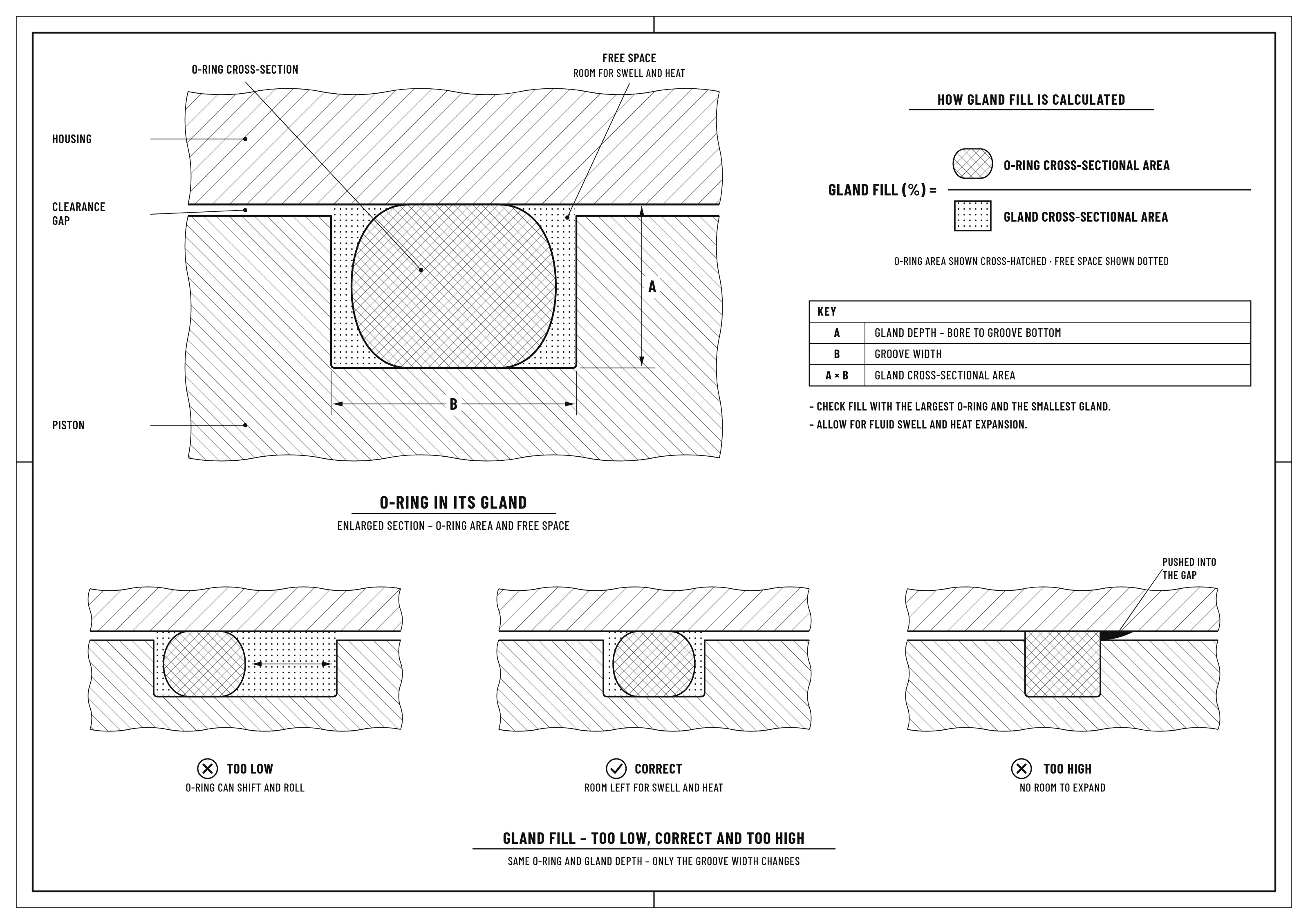
Gland fill is the share of the gland occupied by the O-ring. Rubber is nearly incompressible, so a squeezed O-ring changes shape but not volume and needs free space around it.
Calculation
Gland fill (%) = O-ring cross-sectional area ÷ gland cross-sectional area
General guidance
● A sound O-ring groove design never leaves the gland completely full. Free volume is needed for thermal expansion and fluid swell, as elastomers expand far more than metal.
● High-temperature compounds such as FFKM and fluids known to cause swell, need extra free volume at the O-ring groove sizing stage.
● Vacuum and gas glands often use a narrower groove to limit O-ring movement.
An overfilled gland can result in: extrusion, nibbling, high assembly force and flanges that do not close fully.
An underfilled gland can result in: O-ring rolling with every pressure change, leading to wear and spiral failure in reciprocating seals.
O-Ring Application Pressure and Clearance Gap
The clearance gap is the space between mating parts, such as a piston and its bore. Pressure pushes the O-ring towards this gap. At moderate pressure with a small gap, this improves sealing. With a large gap or high pressure, the elastomer is forced into the gap and extrudes.
The safe gap becomes smaller as pressure rises and also depends on O-ring hardness, temperature and the tear strength of the compound. Silicone and fluorosilicone need especially tight gaps. Thin-walled cylinders expand under pressure, so the running gap can be larger than the O-ring groove dimensions on the drawing suggest.
High Pressure Extrusion
Extrusion can be prevented by:
● Reducing the gap with closer machining or guide bearings.
● Selecting a harder compound.
● Adding back-up rings on the low-pressure side, or on both sides where pressure alternates, with the groove widened to suit.
ISMAT manufactures back-up rings in PTFE, filled PTFE and PEEK grades, in solid, scarf-cut, spiral and concave forms.
Pressure Cycling
Repeated pressure cycles shift the O-ring back and forth, causing wear and nibbling at the gland edge. Abrasion-resistant compounds and correct gland fill reduce this. Clearance checks should be based on peak pressure from valve closures or sudden stops, not only working pressure.
O-Ring Tolerances
Tolerances on the O-ring and on the O-ring groove dimensions decide the real squeeze and gland fill in service. Careful O-ring groove sizing checks both extremes: the largest O-ring in the smallest gland and the smallest O-ring in the largest gland. Smaller cross-sections need tighter machining tolerances; larger ones are more forgiving.
An O-ring groove calculator speeds up these checks, provided it applies tolerances and stretch rather than nominal sizes alone.
O-Ring Gland Surface Finish
A rough surface leaves leak paths and abrades the O-ring in dynamic service.
● Gas and vacuum seals need a smoother finish than liquid seals.
● Dynamic surfaces need the smoothest finish, but a mirror polish cannot hold a lubricating film.
● Groove side walls can be slightly rougher than the sealing surfaces.
● Turned surfaces, with marks running around the groove, seal better than milled surfaces with marks crossing the O-ring path.
● Softer compounds conform better to rougher surfaces.
O-Ring Gland Corners and Lead-In Chamfers
Sharp corners and burrs are among the most common faults in O-ring groove design, and a frequent cause of O-ring damage.
● Groove bottom corners need a small radius so the O-ring seats fully.
● Top edges should be lightly broken, but kept small on the low-pressure side to avoid widening the extrusion gap.
● Bores and rod ends need a smooth, burr-free lead-in chamfer.
● O-rings should not pass over ports, threads or splines unprotected. A smooth mandrel or fitting sleeve prevents cuts and over-stretching.
● Where sharp corners cannot be avoided, a harder compound or a back-up ring reduces the risk of damage.
O-Ring Eccentricity and Side Loading
Parts are never perfectly concentric, so the gland is deeper on one side than the other. Side loads on a piston or rod push them further off-centre. The result is too little squeeze and leakage on one side and too much squeeze, wear and extrusion on the other.
Unless bearings or wear rings keep the parts central, O-ring gland design checks for squeeze and extrusion should assume the full clearance is open on one side, a case where many O-ring groove calculators skip.
Choose ISMAT for O-Rings and Gland Design Support
ISMAT manufactures O-rings in FFKM, FKM, FEPM, HNBR, NBR, EPDM, silicone and other compounds, in standard and non-standard sizes, with matching back-up rings. Our engineers can review your O-ring groove design for squeeze, stretch and fill and recommend the right compound for your fluid, temperature and pressure.
Need help with a gland design? Email inquiry@ismat.in or send us an enquiry.
Get In Touch
TALK TO AN O-RING SPECIALIST
Share your gland details and our engineers will check the squeeze, stretch and gland fill for you.
We supply O-rings in FFKM, FKM, FEPM, HNBR, EPDM, NBR and silicone, with PTFE and PEEK back-up rings, and help you get the O-ring groove design right for your pressure, temperature and media.
