When designing or sourcing equipment for food and beverage production, the selection of sealing materials directly impacts regulatory compliance and product safety. The rubber seals, gaskets and elastomeric components used in your machinery determine whether your equipment meets regulatory requirements and maintains product safety. This is where NSF/ANSI 51 certification becomes critical.
NSF 51 certification verifies that materials will not contaminate food or compromise equipment hygiene—a rigorous public health standard that directly impacts compliance and brand protection. If you are responsible for sourcing, procurement, engineering or new product development in the food and beverage sector, understanding NSF 51 certification is essential to avoiding costly compliance failures.
This blog explains the technical basis of NSF 51, how it applies to rubber sealing components, and what you should evaluate when selecting certified materials for your operations.
What Is NSF/ANSI 51? A Technical Overview
Standard Purpose and Scope
NSF/ANSI 51 is a standard developed jointly by NSF International and the American National Standards Institute (ANSI). It establishes minimum requirements for materials used in commercial food equipment construction—specifically to ensure that equipment materials do not adulterate food and remain sanitary under normal use.
Unlike general quality standards, NSF 51 focuses on public health rather than mechanical performance alone. It evaluates whether a material can safely contact food without leaching harmful substances, whether it can be effectively cleaned, and whether it resists corrosion and degradation in food-contact environments.
What NSF 51 Actually Tests
When a rubber compound undergoes NSF 51 evaluation, the testing laboratory performs specific assessments that measure real-world safety performance.
1. Extractive Residue Testing (US FDA 21 CFR 177.2600)
This is the most critical test for rubber seals and gaskets. It measures whether substances from the rubber material leach into food or food-contact liquids under simulated use conditions.
The test uses two solvents and two temperature regimens:
● Distilled water at reflux (7 hours): Simulates contact with aqueous foods like juices, sauces and beverages. Standard limit: 20.0 mg/inch².
● n-Hexane at reflux (7 hours): Simulates contact with fatty or oily foods. Standard limit: 175.0 mg/inch².
● Distilled water at reflux (2 hours): High-temperature applications. Standard limit: 1.0 mg/inch².
● n-Hexane at reflux (2 hours): Oil-contact at high heat. Standard limit: 4.0 mg/inch².
Any compound exceeding these thresholds fails certification./p>
2. Material Composition Analysis
NSF 51 restricts certain substances in rubber formulations:
● Lead and cadmium are evaluated under NSF/ANSI/CAN 372, with lead content not exceeding 0.25% weighted average in food-contact components.
● Certain plasticizers, colorants and processing aids are restricted or require documented safety data.
3. Cleanability and Corrosion Resistance
Rubber materials must withstand cleaning procedures (hot water, detergents, sanitizers) without degradation and resist common food-processing chemicals and sanitizers.
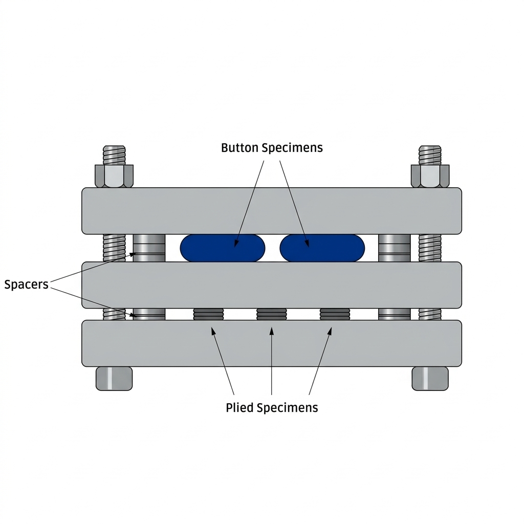
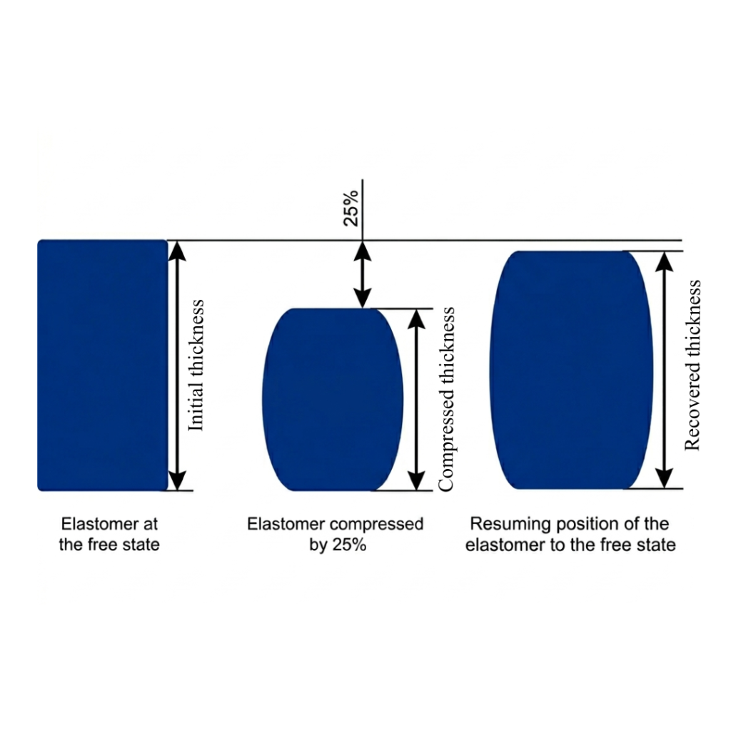
4. Physical Property Retention
Materials must maintain elasticity and hardness after exposure to food-contact conditions. A gasket that hardens, cracks or loses flexibility during use is not compliant.
Why This Matters
A non-certified seal might pass mechanical tests but could leach plasticizers, colorants, or degradation products into food. While tiny quantities may not cause immediate harm, regulatory agencies and product liability concerns make non-compliance costly.
Certified materials provide assurance that your equipment meets FDA guidelines, passes health department inspections, and offers documented proof of food safety compliance—protecting product recalls and liability claims.
NSF 51-Certified Rubber Types in Practice
NSF 51 certification is compound-specific, meaning each elastomer formulation must be tested and approved individually. The most common certified options are:
Widely used in food and beverage equipment seals, NSF 51-certified NBR offers good resistance to oils and fats (suitable for dairy, oils and acidic foods), typical operating temperatures up to 180°F (82°C), and moderate cost. NBR is particularly valued in applications involving acidic foods and aqueous solutions.
Food-grade silicone compounds are extensively NSF 51 certified and offer wider temperature ranges (up to 400°F / 204°C for premium grades), better resistance to extreme temperatures, non-reactivity with most food types, and lower migration of extractive residues. Silicone is preferred in high-temperature applications such as oven gaskets or steam-based equipment.
EPDM (Ethylene Propylene Diene Monomer)
EPDM can be formulated for NSF 51 compliance in applications requiring resistance to steam, hot water, and frequent high-temperature sanitization cycles.
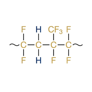
When formulated specifically for food contact, FKM compounds achieve NSF 51 certification in extreme-duty applications requiring superior resistance to aggressive chemicals, high-temperature performance, and resistance to ozone and UV degradation.
Each elastomer type has specific food-contact limitations defined in its NSF 51 listing—some compounds approve only for “aqueous acidic” foods, while others cover “all foods.”
Where NSF 51-Certified Seals Are Used
Beverage Systems
Rubber gaskets and seals are critical in beverage dispensers, smoothie machines, juice extractors, coffee and espresso machine components, carbonation systems, and steam valve assemblies. These seals must withstand high temperatures (steam reaching 212°F / 100°C), prolonged contact with acidic beverages, regular cleaning with hot water and chemical sanitizers, and oils from milk or cream.
Dairy Processing Equipment
Dairy seals must resist milk proteins and lactose, alkaline cleaning-in-place (CIP) systems, and temperature cycling between refrigeration and processing heat. Certified compounds ensure milk products are not contaminated by leached materials, protecting product quality and shelf life.
Ovens, Steamers and High-Heat Equipment
Oven gaskets and steamer door seals face sustained temperatures of 350–500°F (176–260°C), repeated thermal cycling, and contact with moisture and food particles. Only premium NSF 51-certified compounds (typically silicone or specialized FKM formulations) retain structural integrity under these conditions.
Food Processing Machinery
Industrial rubber seals are used in mixers, blenders, homogenizers, bottling and canning equipment, and dry goods handling systems. Each application has specific material requirements—a seal suitable for dry goods may not perform in oily environments, and a 180°F-rated gasket will fail in a 250°F steamer.
Wash-Down and Sanitation Equipment
Gaskets in dishwashing machines and high-pressure wash systems must resist caustic and acidic cleaning chemicals, maintain elasticity under 160–180°F water exposure, and not degrade or absorb detergent residues.
NSF 51-Certified vs. Non-Certified Seals: Key Differences
| Factor | NSF 51-Certified | Non-Certified |
|---|---|---|
| Extractive Testing | Verified by third party; documented results available | Not tested; unknown leaching profile |
| Food Type Approval | Specific approval for defined food types | No regulated food-contact claim |
| Maximum Temperature | Defined and tested | Unknown performance limits |
| Regulatory Compliance | Meets FDA 21 CFR 177.2600 | May not align with FDA requirements |
| Quality Consistency | Batch testing and documentation | Depends on supplier controls |
| Liability and Insurance | Clear compliance documentation; reduced liability risk | Potential regulatory and liability exposure |
Non-certified materials create hidden risks: regulatory inspection failures, product liability exposure, supply chain disruption, and quality inconsistency. Health department inspectors expect documentation of NSF 51 compliance, and failure to provide it can trigger recalls or lawsuits.
Selecting the Right Seal for Your Application
Key Questions to Guide Your Decision
1. What food types will the seal contact?
● Aqueous foods (beverages, soups, sauces)?
● Acidic foods (citrus, tomatoes, vinegar)?
● Fatty or oily foods (dairy, cooking oils)?
● Dry solids (grains, flour, sugar)?
Each NSF 51 listing specifies approved food types. A seal rated for “all foods” is more versatile but typically more expensive.
2. What is the maximum operating temperature?
● 180°F (82°C): Common for many NBR and EPDM formulations.
● 212°F (100°C): Suitable for steam and hot water applications.
● 300°F+ (149°C+): Premium silicone or FKM compounds for high-heat equipment.
Specifying a seal rated below your actual operating temperature leads to hardening and seal failure.
3. What cleaning and sanitization methods will be used?
● Hot water and mild detergent?
● Alkaline or acidic CIP solutions?
● Chemical sanitizers?
● High-pressure steam?
Some rubber compounds are sensitive to specific sanitizers—verify your chosen material tolerates your facility’s methods.
4. What is the expected service life?
Balance material cost against replacement frequency and labor costs. Some NSF 51-certified compounds prioritize durability, others emphasize cost efficiency.
5. Are there surface finish or aesthetic requirements?
NSF 51 certified compounds are available in various colors. Ensure your selected compound is available in the required finish without compromising certification.
Understanding Third-Party Testing and Accreditation
NSF 51 certification is performed by accredited laboratories (TUV NORD, NSF International, and others) using standardized protocols. These independent laboratories ensure unbiased testing through:
● Reproducibility: Standardized equipment and methods enable consistent comparison across compounds.
● Traceability: Complete documentation creates a verifiable chain of custody.
● Accreditation: Regular audits verify laboratories follow established protocols.
When reviewing a test report, verify that all four test conditions (7-hour water, 7-hour hexane, 2-hour water, 2-hour hexane) are present with numerical results, pass/fail conclusions and authorized signatures. Incomplete testing should not be accepted.
Partner with ISMAT for NSF 51-Certified Solutions
NSF 51 certification is a foundational element of food and beverage equipment safety. For procurement teams, engineers, and sourcing managers, the process of selecting NSF 51-certified seals involves five core steps:
● Understand the specific food types and temperature range your application requires.
● Request and verify NSF 51 certificates and FDA extractive residue test reports.
● Evaluate compound options (NBR, silicone, EPDM, FKM) based on performance and cost.
● Build NSF 51 compliance into specifications and purchase orders.
● Maintain documentation for regulatory audits.
The investment in certified materials is repaid through reduced regulatory risk, improved customer confidence, and elimination of product liability exposure.
ISMAT, with over 40 years of expertise in high-performance sealing solutions, offers NSF 51-certified compounds and sealing products designed for the food and beverage industry. Our offerings include:
● NSF 51-certified rubber compounds (nitrile, silicone, EPDM, FKM) with documented FDA 21 CFR 177.2600 compliance .
● Custom O-rings, gaskets, valve seats and complex profiles manufactured to specification.
● Complete documentation including NSF certificates, extractive residue test reports and technical data sheets.
Our sealing solutions serve equipment manufacturers, food processors and operators across dairy, beverages, ovens, steamers, processing equipment and washdown systems.
For detailed information on NSF 51-certified compounds and custom sealing solutions tailored to your application, visit www.ismat.in or contact our technical team. We maintain strict quality control and continuous certification to ensure your equipment meets the highest food safety standards.